A sand casting or a sand molded casting is a cast part produced by forming a mold from a sand mixture and pouring molten liquid metal into the cavity in the mold. The mold is then cooled until the metal has solidified. In the last stage the casting is separated from the mold. There are six steps in this process:
-
Place a pattern in sand to create a mold.
-
Incorporate a gating system.
-
Remove the pattern.
-
Fill the mold cavity with molten metal.
-
Allow the metal to cool.
-
Break away the sand mold and remove the casting.
There are two main types of sand used for molding. "Green sand" is a mixture of silica sand, clay, moisture and other additives. The "air set" method uses dry sand bonded to materials other than clay, using a fast curing adhesive. When these are used, they are collectively called "air set" sand castings to distinguish these from "green sand" castings. Two types of molding sand are natural bonded (bank sand) and synthetic (lake sand), which is generally preferred due to its more consistent composition.
With both methods, the sand mixture is packed around a master "pattern" forming a mold cavity. If necessary, a temporary plug is placed to form a channel for pouring the fluid to be cast. Air-set molds often form a two-part mold having a top and bottom, termed Cope and drag. The sand mixture is tamped down as it is added, and the final mold assembly is sometimes vibrated to compact the sand and fill any unwanted voids in the mold. Then the pattern is removed with the channel plug, leaving the mold cavity. The casting liquid (typically molten metal) is then poured into the mold cavity. After the metal has solidified and cooled, the casting is separated from the sand mold. There is typically no mold release agent, and the mold is generally destroyed in the removal process.[1]
The accuracy of the casting is limited by the type of sand and the molding process. Sand castings made from coarse green sand impart a rough texture on the surface of the casting, and this makes them easy to identify. Air-set molds can produce castings with much smoother surfaces. Surfaces can also be ground and polished, for example when making a large bell. After molding, the casting is covered in a residue of oxides, silicates and other compounds. This residue can be removed by various means, such as grinding, or shot blasting.
During casting, some of the components of the sand mixture are lost in the thermal casting process. Green sand can be reused after adjusting its composition to replenish the lost moisture and additives. The pattern itself can be reused indefinitely to produce new sand molds. The sand molding process has been used for many centuries to produce castings manually. Since 1950, partially-automated casting processes have been developed for production lines.
Simple manual sand casting process
Patterns
From the design, provided by an engineer or designer, a skilled pattern maker builds a pattern of the object to be produced, using wood, metal, or a plastic such as expanded polystyrene. Sand can be ground, swept or even strickled into shape. The metal to be cast will contract during solidification, and this may be non-uniform due to uneven cooling. Therefore, the pattern must be slightly larger than the finished product, a difference known as contraction allowance. Pattern-makers are able to produce suitable patterns using 'Contraction rules' (these are sometimes called "shrink allowance rulers" where the ruled markings are deliberately made to a larger spacing according to the percentage of extra length needed). Different scaled rules are used for different metals because each metal and alloy contracts by an amount distinct from all others. Patterns also have core prints that create registers within the molds into which are placed sand 'cores. Such cores, sometimes reinforced by wires, are used to create under cut profiles and cavities which cannot be molded with the cope and drag, such as the interior passages of valves or cooling passages in engine blocks.
Paths for the entrance of metal into the mold cavity constitute the runner system and include the sprue, various feeders which maintain a good metal 'feed', and in-gates which attach the runner system to the casting cavity. Gas and steam generated during casting exit through the permeable sand or via risers, which are added either in the pattern itself, or as separate pieces.

Cope & drag (top and bottom halves of a sand mold), with cores in place on the drag
Molding box and materials
A multi-part molding box (known as a casting flask, the top and bottom halves of which are known respectively as the cope and drag) is prepared to receive the pattern. Molding boxes are made in segments that may be latched to each other and to end closures. For a simple object��flat on one side��the lower portion of the box, closed at the bottom, will be filled with prepared casting sand or green sand��a slightly moist mixture of sand and clay. The sand is packed in through a vibratory process called ramming and, in this case, periodically screeded level. The surface of the sand may then be stabilized with a sizing compound. The pattern is placed on the sand and another molding box segment is added. Additional sand is rammed over and around the pattern. Finally a cover is placed on the box and it is turned and unlatched, so that the halves of the mold may be parted and the pattern with its sprue and vent patterns removed. Additional sizing may be added and any defects introduced by the removal of the pattern are corrected. The box is closed again. This forms a "green" mold which must be dried to receive the hot metal. If the mold is not sufficiently dried a steam explosion can occur that can throw molten metal about. In some cases, the sand may be oiled instead of moistened, which makes possible casting without waiting for the sand to dry. Sand may also be bonded by chemical binders, such as furane resins or amine-hardened resins.
Chills
To control the solidification and metallurgical structure of the metal, it is possible to place metal plates��chills�� in the mold. The associated rapid local cooling will form a finer-grained structure and may form a somewhat harder metal at these locations. In ferrous castings the effect is similar to quenching metals in forge work. The inner diameter of an engine cylinder is made hard by a chilling core. In other metals chills may be used to promote directional solidification of the casting. In controlling the way a casting freezes it is possible to prevent internal voids or porosity inside castings.
Cores
To produce cavities within the casting��such as for liquid cooling in engine blocks and cylinder heads��negative forms are used to produce cores. Usually sand-molded, cores are inserted into the casting box after removal of the pattern. Whenever possible, designs are made that avoid the use of cores, due to the additional set-up time and thus greater cost.

Two sets of castings (bronze and aluminium) from the above sand mold
With a completed mold at the appropriate moisture content, the box containing the sand mold is then positioned for filling with molten metal��typically iron, steel, bronze, brass, aluminium, magnesium alloys, or various pot metal alloys, which often include lead, tin, and zinc. After filling with liquid metal the box is set aside until the metal is sufficiently cool to be strong. The sand is then removed revealing a rough casting that, in the case of iron or steel, may still be glowing red. When casting with metals like iron or lead, which are significantly heavier than the casting sand, the casting flask is often covered with a heavy plate to prevent a problem known as floating the mold. Floating the mold occurs when the pressure of the metal pushes the sand above the mold cavity out of shape, causing the casting to fail.
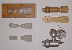
Left:- Corebox, with resulting (wire reinforced) cores directly below. Right:- Pattern (used with the core) and the resulting casting below (the wires are from the remains of the core)
After casting, the cores are broken up by rods or shot and removed from the casting. The metal from the sprue and risers is cut from the rough casting. Various heat treatments may be applied to relieve stresses from the initial cooling and to add hardness��in the case of steel or iron, by quenching in water or oil. The casting may be further strengthened by surface compression treatment��like shot peening��that adds resistance to tensile cracking and smooths the rough surface.
Design requirements
The part to be made and its pattern must be designed to accommodate each stage of the process, as it must be possible to remove the pattern without disturbing the molding sand and to have proper locations to receive and position the cores. A slight taper, known as draft, must be used on surfaces perpendicular to the parting line, in order to be able to remove the pattern from the mold. This requirement also applies to cores, as they must be removed from the core box in which they are formed. The sprue and risers must be arranged to allow a proper flow of metal and gasses within the mold in order to avoid an incomplete casting. Should a piece of core or mold become dislodged it may be embedded in the final casting, forming a sand pit, which may render the casting unusable. Gas pockets can cause internal voids. These may be immediately visible or may only be revealed after extensive machining has been performed. For critical applications, or where the cost of wasted effort is a factor, non-destructive testing methods may be applied before further work is performed.
Types of molds
Green sand
These molds are made of wet sands that are used to make the mold's shape. The name comes from the fact that wet sands are used in the molding process.
Cold box
Uses organic and inorganic binders that strengthen the mold by chemically adhering to the sand. This type of mold gets its name from not being baked in an oven like other sand mold types. This type of mold is more accurate dimensionally than green-sand molds but are more expensive.
No bake molds
No bake molding is a type of molding used for the casting of molten metals. Like sand casting it is an expendable mold that is made up of sand. The primary difference is that it keeps its form from having a liquid resin mixed with the sand at room temperature to help keep its form. Because no heat is involved it called a cold-setting processes. This type of molding also produces a better surface finish than other types of sand molds, and due to the binder does not need to be baked in an oven. Common flask materials that are used are wood, metal, or plastic. Common metals cast into no bake molds are brass, ferric, and aluminium alloys.
Essential improvements of the foundry technology
In 1924 the Ford automobile company set a record by producing 1 million cars, in the process consuming one-third of the total casting production in the U.S. As the automobile industry grew the need for increased casting efficiency grew. The increasing demand for castings in the growing car and machine building industry during and after World War I and World War II, stimulated new inventions in mechanization and later automation of the sand casting process technology.
There was not one bottleneck to faster casting production but rather several. Improvements were made in molding speed, molding sand preparation, sand mixing, core manufacturing processes, and the slow metal melting rate in cupola furnaces. In 1912 the sand slinger was invented by the American company Birdsley & Piper. In 1912 the first sand mixer with individually mounted revolving plows was marketed by the Simpson Company. In 1915 the first experiments started with bentonite clay instead of simple fire clay as the bonding additive to the molding sand. This increased tremendously the green and dry strength of the molds. In 1918 the first fully automated foundry for fabricating hand grenades for the U.S. Army went into production. In the 1930s the first high-frequency coreless electric furnace was installed in the U.S. In 1943 ductile iron was invented by adding magnesium to the widely used grey iron. In 1940 thermal sand reclamation was applied for molding and core sands. In 1952 the "D-process" was developed for making shell molds with fine, pre-coated sand. In 1953 the hotbox core sand process in which the cores are thermally cured was invented. In 1954 a new core binder - water glass hardened with CO2 from the ambient air, was applied.
Fast molding & sand casting processes
With the fast development of the car and machine building industry the casting consuming areas called for steady higher productivity. The basic process stages of the mechanical molding and casting process are similar to those described under the manual sand casting process. The technical and mental development however was so rapid and profound that the character of the sand casting process changed radically.
Mechanized sand molding
The first mechanized molding lines consisted of sand slingers and/or jolt-squeeze devices that compacted the sand in the flasks. Subsequent mould handling was mechanical using cranes, hoists and straps. After core setting the copes and drags were coupled using guide pins and clamped for closer accuracy. The moulds were manually pushed off on a roller conveyor for casting and cooling.
Automatic high pressure sand molding lines
Increasing quality requirements made it necessary to increase the mould stability by applying steadily higher squeeze pressure and modern compaction methods for the sand in the flasks. In early fifties the high pressure molding was developed and applied in mechanical and later automatic flask lines. The first lines were using jolting and vibrations to precompact the sand in the flasks and compressed air powered pistons to compact the molds.
Horizontal sand flask molding
In the first automatic horizontal flask lines the sand was shot or slung down on the pattern in a flask and squeezed with hydraulic pressure of up to 140 bars. The subsequent mould handling including turn-over, assembling, pushing-out on a conveyor were accomplished either manually or automatically. In the late fifties hydraulically powered pistons or multi-piston systems were used for the sand compaction in the flasks. This method produced much more stable and accurate molds than it was possible manually or pneumatically. In the late sixties mold compaction by fast air pressure or gas pressure drop over the pre-compacted sand mold was developed (sand-impulse and gas-impact). The general working principle for most of the horizontal flask line systems is shown on the sketch below.
Today there are many manufacturers of the automatic horizontal flask molding lines. The major disadvantages of these systems is high spare parts consumption due to multitude of movable parts, need of storing, transporting and maintaining the flasks and productivity limited to approximately 90 �C120 molds/hour per molding unit.
Vertical sand flaskless molding
In the end of the fifties foundry industry, as all the others, called constantly for reduction of the labor costs, higher productivity casting quality and improved dimensional accuracy. Due to constantly increasing wages reduction of the human labor became important. This required automation. In 1962 Danish company Dansk Industri Syndikat A/S (DISA) implemented an ingenious idea of molding without flasks applying vertically parted and poured moulds. The first automatic DISA molding line could produce up to 240 complete sand molds per hour. Today a modern DISA molding line can achieve a molding rate of 550 sand molds per hour (one complete mold for each 6.5 seconds) and requires only one monitoring operator. Maximal mismatch of two half��s of the castings made on the DISA lines does not exceed 0.1 mm. Apart from the high productivity, low labor requirement and dimensional castings accuracy DISA vertical flaskless moulding lines are very reliable (up to 98% in efficiency].
Virtually there are no other serious manufacturers of the vertical flaskless molding lines but the Danish DISA Industries.
Matchplate sand molding
The principle of the matchplate, meaning pattern plates with two patterns on each side of the same plate, was developed and patented in 1910, fostering the perspectives for future sand molding improvements. However first in the early sixties the American company Hunter Automated Machinery Corporation launched its first automatic flaskless, horizontal molding line applying the matchplate technology. The method alike to the DISA's vertical moulding is flaskless, however horizontal. It has been improved by several producers.The main suppliers are the DISA Industries, Hunter Automated Machinery and Heinrich Wagner Sinto. The matchplate molding technology is today used widely, particularly in the U.S., China and India. Its great advantage is inexpensive pattern tooling, easiness of changing the molding tooling, thus suitability for manufacturing castings in short series so typical for the jobbing foundries. Modern matchplate molding machine is capable of high molding quality, less casting shift due to machine-mold mismatch (in some cases even 0.15 mm or less), consistently stable molds for less grinding and improved parting line definition. In addition, the machines are enclosed for a cleaner, quieter working environment with reduced operator exposure to safety risks or service-related problems.
Decorative use of wood patterns
Some collectors seek obsolete hardwood patterns, once used to make molds for casting machine parts, to use as interior decorations. These are valued due to the fine woodworking involved, sometimes interesting sculptural shapes of decorative embelishments, and the display of the grain of the wood.
Alternative casting methods
As a supplement to the sand casting other casting methods were successfully applied.
-
Modern casting production methods can manufacture thin and accurate molds��of a material superficially resembling papier-mâch��, such as is used in egg cartons, but that is refractory in nature��that are then supported by some means, such as dry sand surrounded by a box, during the casting process. Due to the higher accuracy it is possible to make thinner and hence lighter castings, because extra metal need not be present to allow for variations in the molds. These thin-mold casting methods have been used since the 1960s in the manufacture of cast-iron engine blocks and cylinder heads for automotive applications.
-
Increasingly in modern production, various automotive components are frequently made of aluminium, which for appropriately shaped components may be made either by sand casting or by die casting, the latter an accurate process that greatly reduces both materials use and machining and finishing costs. While the material and the processing setup is more expensive than the use of iron this is one of the most straightforward ways to reduce weight in a vehicle, important as a contributor to both fuel economy and acceleration performance. For front engine vehicles with rear wheel drive the improvement in weight distribution can improve both handling and traction. For all configurations weight saved in the engine is multiplied in that this enables use of lighter suspension components which in turn improves suspension response by reducing unsprung weight
-
Starting in the early 1980s, some castings such as automotive engine blocks have been made using a sand casting technique conceptually similar to the lost wax process, known as the lost foam process. In this process, the pattern is made of polystyrene foam, around which the sand is packed, leaving the foam in place. When the metal is poured into the mold, the heat of the metal vaporizes the foam a short distance away from the surface of the metal, leaving the molding cavity into which the metal flows. The lost-foam process supports the sand much better than conventional sand casting, allowing greater flexibility in the design of the cast parts, with less need for machining to finish the casting. This technique was developed for the green sand mold casting of sculpture and was first adopted for large quantity commercial production by the Saturn Corporation.
-
Vacuum molding process, popularly known as V-process, is a sand molding process, in which unbonded sand is held in place in the mold by a vacuum. In this process the pattern is covered by a tightly conforming thin sheet of plastic film which is applied with vacuum after being heated. The film, conforming to the shape of the pattern, may have a refractory coating applied which is dried before filling the flask with sand. A flask is placed over the plastic coated pattern, and is filled with free-flowing sand, with vibration for compaction. Another sheet of plastic is placed over the top of the sand in the flask and the flask is evacuated. The vacuum "hardens" (compacts) the sand so the pattern can be withdrawn, the vacuum holding the film to the pattern being released at this time. The other half of the mold is made the same way. After cores are set in place, the mold is closed and poured while still under vacuum. When the metal has solidified, the vacuum is turned off and the sand runs out freely, releasing the casting. The V-process is known for the high dimensional tolerances and good surface finish of the castings. Due to multiplicity of operations it is suitable for low to medium production volumes, depending on the amount of conveyorized equipment within the foundry. Because the sand never touches the pattern itself, there is almost no pattern wear. Minimal or zero draft allowance can be used on vertical surfaces.
-
Shell molding process' principle is applied, when a heated (200 ��C / 392 ��F) metal pattern is covered with a mixture of sand and thermoset plastic (sometimes the sand is precoated with this mixture). This causes a skin of about 3.5 mm (0.125 in) of sand/plastic mixture to adhere to the pattern. This skin is removed from the pattern to form the "shell mold". The two halves of the shell mold are matched and secured together and the metal is poured in the shell to form the casting. Once the casting solidifies, the shell is broken and the sand can be regenerated. Shell molding process offers good surface finish, good dimensional tolerances, however the productivity is incomparable with the automatic green sand molding processes and fairly high capital investment is required. |

 ���������� 31011502006706��


